EL Display on PCB Tutorial
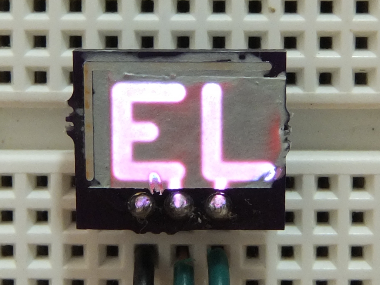
Electroluminescent displays are bright, thin, and versatile. Like EL wire, they emit their own light and are quite striking in the dark. Normally, EL displays are made by silkscreening ink onto a piece of ITO film, a process that requires a lot of setup and expensive equipment. With these displays, the illumination pattern controlled by the silkscreen; wherever the phosphor is present, the display will light up.
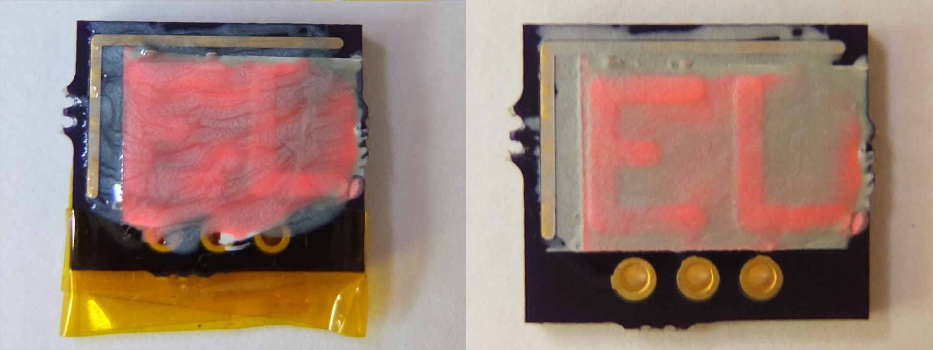
This tutorial will show you how to make a custom electroluminescent display on a PCB. The illumination pattern is defined by the copper layer on the PCB, not where the EL phosphor is deposited. This means that no silkscreen is required, and the ink can be painted on with a brush.
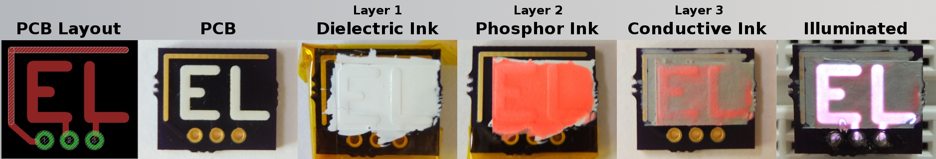
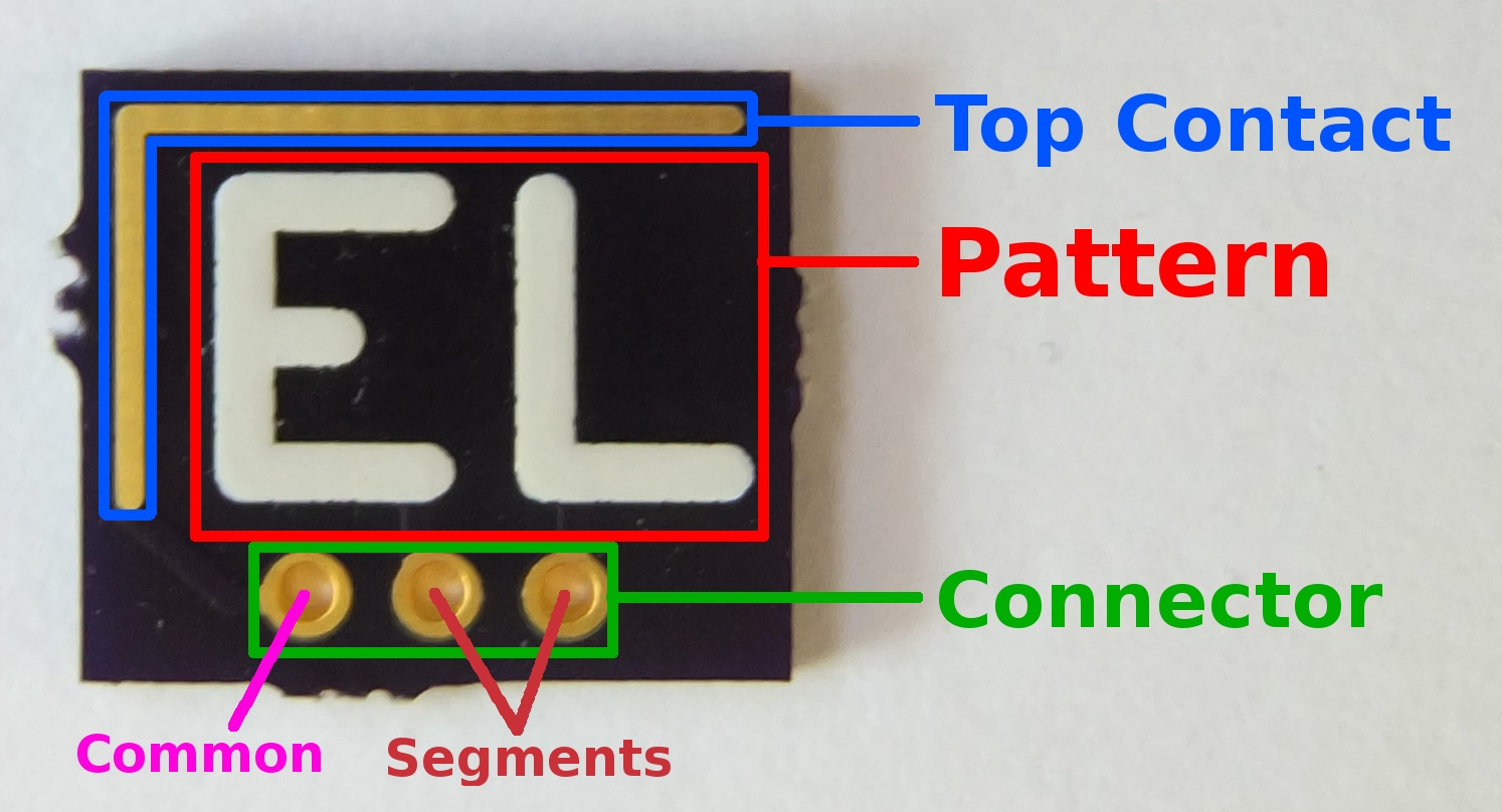
The display is composed of three layers of ink on a PCB. The PCB's copper layer is the bottom plate of the EL capacitor, causing the EL phosphor to glow only where copper is present. The first ink layer is the dielectric, which makes the display glow brighter by increasing the energy stored in the EL capacitor. (If you are using a homemade PCB without soldermask the dielectric layer also insulates the pattern.) After the dielectric comes the phosphor; this is the part that glows. The top layer is a translucent conductive ink, which forms the top plate of the EL capacitor while allowing light from the phosphor to pass through. The top layer touches an exposed track that runs alongside the pattern, connecting it to the power supply.
The EL inks used in this tutorial are the LuxPrint series manufactured by DuPont, but
buying from DuPont requires a large minimum order. I've created an
inexpensive kit to make these inks available to hobbyists. It contains
almost everything you need to make EL displays.
Update 2014-06-02: All the EL kits have been sold. Due to a large increase in the price of Dupont's EL ink, I've decided not to make another batch. Please contact Dupont MCM or Tekra, their new distributor, if you want to buy EL inks.
This process was originally demonstrated by the inimitable Jeri Ellsworth [1]. She has also made several other interesting videos about electroluminescence; see references [2-4].
Materials and Supplies
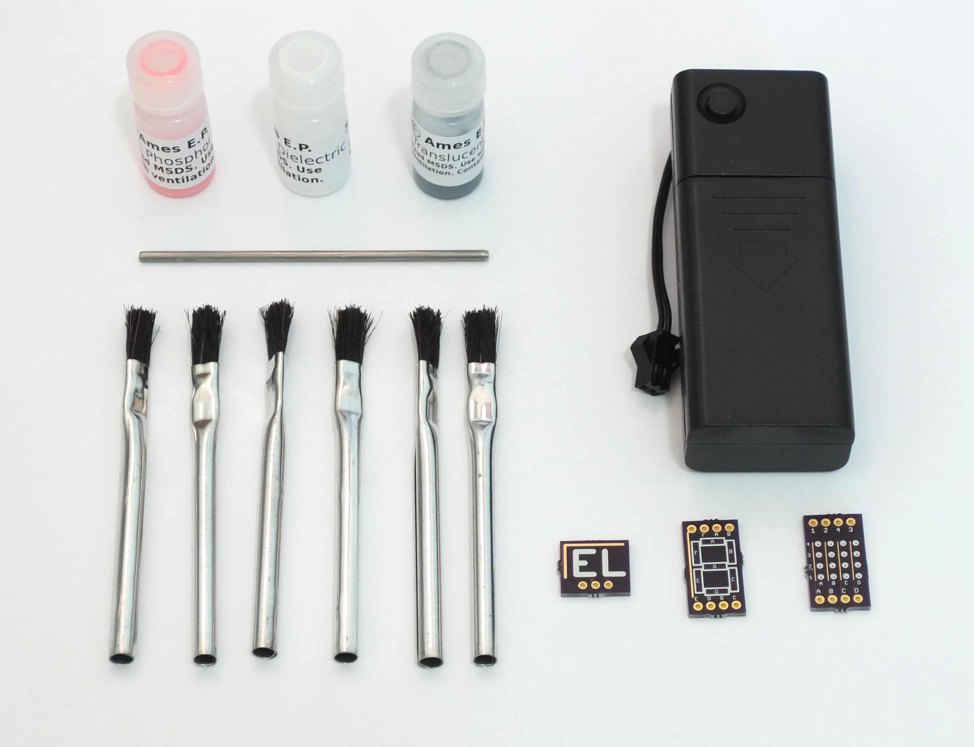
You will need the following items:
- EL Phosphor Ink
- Dielectric Ink
- Translucent Conductive Ink
- Brushes
- Mixing Rod
- EL Power Supply
- PCB
- Kapton Tape (optional)
- Clear Acrylic Spray (optional)
- Acetone (for cleanup)
- Paper Towels or Rags (for cleanup)
- Oven or Heat Gun (Do not use an oven used for cooking food.)
- Well-Ventilated Area
Safety
Read the MSDS sheets included in the documentation file before starting. Apply the inks in a well-ventilated area. Do not use an oven used for food, as the process may leave residues in the oven. The translucent conductor contains Antimony, a heavy metal. Wash hands after handling.
Procedure
Preparation
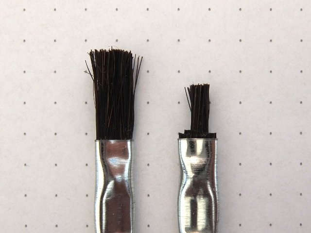
Before starting, trim your brushes (using a sharp pair of scissors) as illustrated in the image below. Shortening the bristles makes them stiffer, increasing control over where the ink is deposited. Trimming the width of the bristles reduces the amount of ink that is trapped and wasted.
Preheat your oven to 110°C-130°C (230°F-270°F).
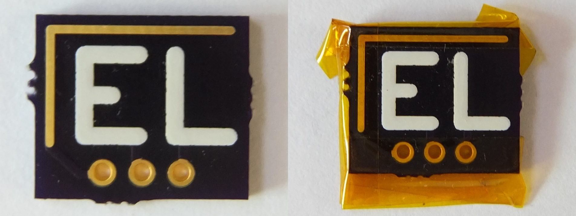
Kapton Tape
If you are using Kapton tape, apply it now. Place a layer of tape over the board's connector, to prevent it from being fouled by the inks. Place a second layer of tape over the top contact, to prevent the dielectric or phosphor inks from covering it.
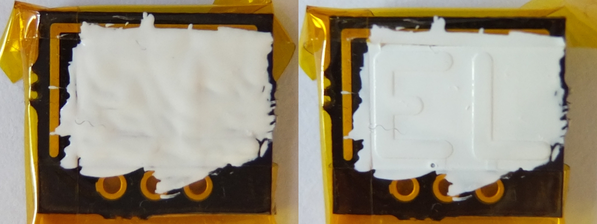
Dielectric Ink
Open the dielectric ink and mix well. Spread the dielectric ink over the pattern area, taking care to avoid the connector and top contact (if not covered with tape). If the PCB uses vias they should be filled with the dielectric. This layer does not need to be very thick. Don't worry about brush marks in the ink; these will even out during baking.
Bake the dielectric layer for 15 minutes at 110°C-130°C (230°F-270°F).
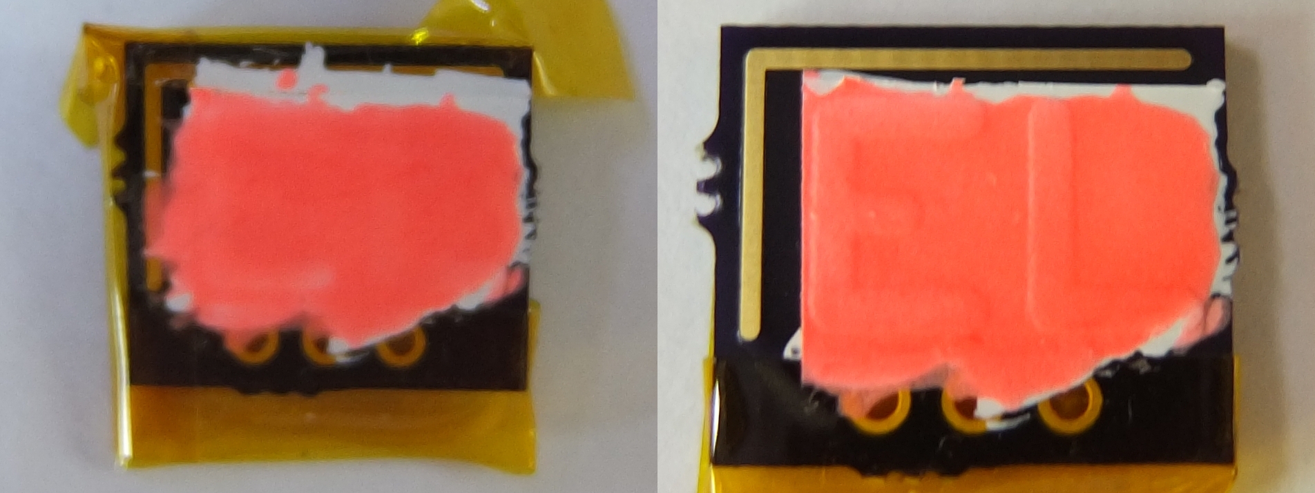
Phosphor Ink
Open the phosphor ink and mix well. Spread the phosphor ink over the pattern area, taking care to avoid the connector and top contact (if not covered with tape). The phosphor layer should be a bit thicker than the dielectric, and the phosphor particles should be evenly distributed.
Bake the phosphor layer for 15 minutes at 110°C-130°C (230°F-270°F).
Translucent Conductor Ink
If you are using Kapton tape, remove the tape from the top contact. Open the translucent conductor ink and mix well. Spread the ink over the pattern area and top contact, taking care to avoid the connector (if not covered with tape). This layer should be very thin. If the layer is too thick, the EL display will be dim.
Bake the translucent conductor layer for 15 minutes at 110°C-130°C (230°F-270°F). If bubbles appear in the layer after baking, the previous layers were not baked long enough.
Connection
After baking the translucent conductive layer the display is ready to use. Connect the display to the EL power supply using wires or a pin header. One power supply lead should connect to the common terminal, and the other should be connected to the terminals of segments you want to illuminate.
If your display does not light up, the most likely problem is a short between the top conductor and one of the segments. To find the problem, use a multimeter to test the resistance between each segment and the common terminal. The resistance should be greater than 200kΩ. A short circuit can be caused by the top conductor touching one of the segment terminals, a via that did not get filled with dielectric, incomplete dielectric coverage, or too little baking time for the dielectric layer. A good dielectric layer is vital for homemade PCBs.
Protection
The bare ink is vulnerable to abrasion and moisture. Use a clear acrylic spray (such as Krylon ColorMaster Acrylic Crystal Clear) to protect the display. Spray an even coat over the display and leave it on a level surface to dry.
PCB Design Tips
- All parts of the pattern must be connected to the power supply.
- The pattern should be covered with soldermask to reduce the chance of short circuits.
- The top contact must not be covered with solder mask.
- Use the smallest vias possible.
- Use tented vias (vias covered with soldermask).
References and Links
- "Printed Circuit Board EL Display - Lets Make Retro Hand Held Games". Jeri Ellsworth, 2010.
https://www.youtube.com/watch?v=h4O3BGjxd5I - "EL Displays - The Stack Up". Jeri Ellsworth, 2010.
https://www.youtube.com/watch?&v=GOYnBAEu3Xs - "Make Electroluminescent (EL) Ink at Home - Re-doping Glow Powder". Jeri Ellsworth, 2010.
https://www.youtube.com/watch?v=pmQqdYrn9g8 - "Making EL Wire Step by Step - Twist and Shout". Jeri Ellsworth, 2010.
https://www.youtube.com/watch?v=cV2HS7_Mg6o - "Electroluminescent Screen Video Tutorial". Zurich University of the Arts, 2013.
https://www.youtube.com/watch?v=ZesXSJ0inBg - EL Ink Documentation File.
EL Display Kit Documentation.zip - "Processing Guide for DuPont Luxprint® Electroluminescent Inks". DuPont Microcircuit Materials, 2012.
Dupont_LuxPrint_EL_Processing_Guide.pdf